Ratul Hora #2
Aim:
Flexible Development of a “Ventilation Path” as a countermeasure against Urban Heat Island (UHI) for the previously proposed “High Density” City Block Planning.

Background:
Urban Heat Island (UHI) and Heat Island Potential (HIP)
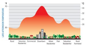
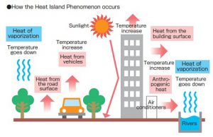
HIP was a calculation introduced by Mr. Hoyano of Tokyo University of Technology which gives us a macro view of the degree of the heat island effect. All the “heat emitting factors” listed above are considered and the surface temperatures of all the outward facing surfaces is calculated (meshes). The temperature difference between the surfaces (each mesh) and the atmospheric temperature is then simulated and then divided by the projected plane area of the city block. This gives a basic idea of the degree of urban heat island effect or in this case as its appropriate name, Heat Island Potential. The Formula is as given below. Note: This software can also simulate and calculate MRT, but as it is not used in this thesis, it will not be explained in further detail. Fig 1, Fig 2, Fig 3
 fig 1
fig 1
 fig 2
fig 2
 fig 3
fig 3
Current Countermeasures:
- Increase in greenery in order to convert sensible heat to latent heat. Issues include increase in management cost and virtually impossible in areas with water scarcity.
- Installation of surfaces that reflect or convert solar insolation to latent heat. Issues include high capital cost for installation process.
- Decrease in heat exhaustion due to human activity. The actual heat exhausted is very minimal in comparison to the solar insolation absorbed by the concrete and asphalt surfaces
- Planning of a “Wind Path” or “Ventilation Path” in order to take exhaust heat out of city using convection. Since it required a large change in the entire urban fabric, it is a very long term solution. Very hard to implement in already developed cities.
Data:
Create Preliminary Urban Models (systematic not compositional).
Run them through “Prevailing Wind Simulations”
Since it is extremely hard to take in account “Transient Wind Flow” and “Transient Heat Flow” during the simulation. Run the simulations initially for only Improvement of wind flow itself (Which include the variables of (Vmag, P)). After we have settled on 3-4 major cases, we can start taking heat into account.
Definitions:
It is hard to define wind flow improvement when heat is not being taken into account in the preliminary phase of the testing. Therefore, there are a few options we have available.
Method 1:
Wind Tunnel Inlet and Outlet Wind Analysis. Analyze the pressure and wind speed at the inlet and outlet surfaces of the wind tunnel model.
Method 2:
Involves looking at the cumulative frequency graph of all the different colored pixels (which represent velocity magnitudes) and determine a broader definition for the how well the ventilation has improved.
Stuttgart’s Ventilation Path (Urban Scale):
- Aerodynamic roughness Length of all surfaces need to be under 50cm
- The ventilation path needs to be atleast 1000m in length and 50m in width. Building corners are to be smoothened out
- If any obstacle is to be placed in the wind path, its width should be under 10% of the wind path and under 10m in height.
- If such obstacles are to be lined up in the wind path, buildings need to have a They need to have a gap of at least 0.1XHeight of Obstacle in the case of buildings and 0.2XHeight of Obstacle in the case of trees.
Reading suggested by Sakaushi Sensei:
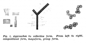
Investigations in the Collective Form, Fumihiko Maki Fig 10
Which is subdivided into
- Compositional Form
- Mega Form
- Group Form
Linkage and Collective Form Fig 11
- To Mediate
- To Define
- To Repeat
- Sequential Path
- To Select

fig 4
fig 5
Current Issues:
What scale to design at?
This will dictate the entire future process of this thesis/design, which software to use, and what kind of conclusion to derive.